

E-Wifi Dongle

Current Transformer: Precision, Safety, Efficiency


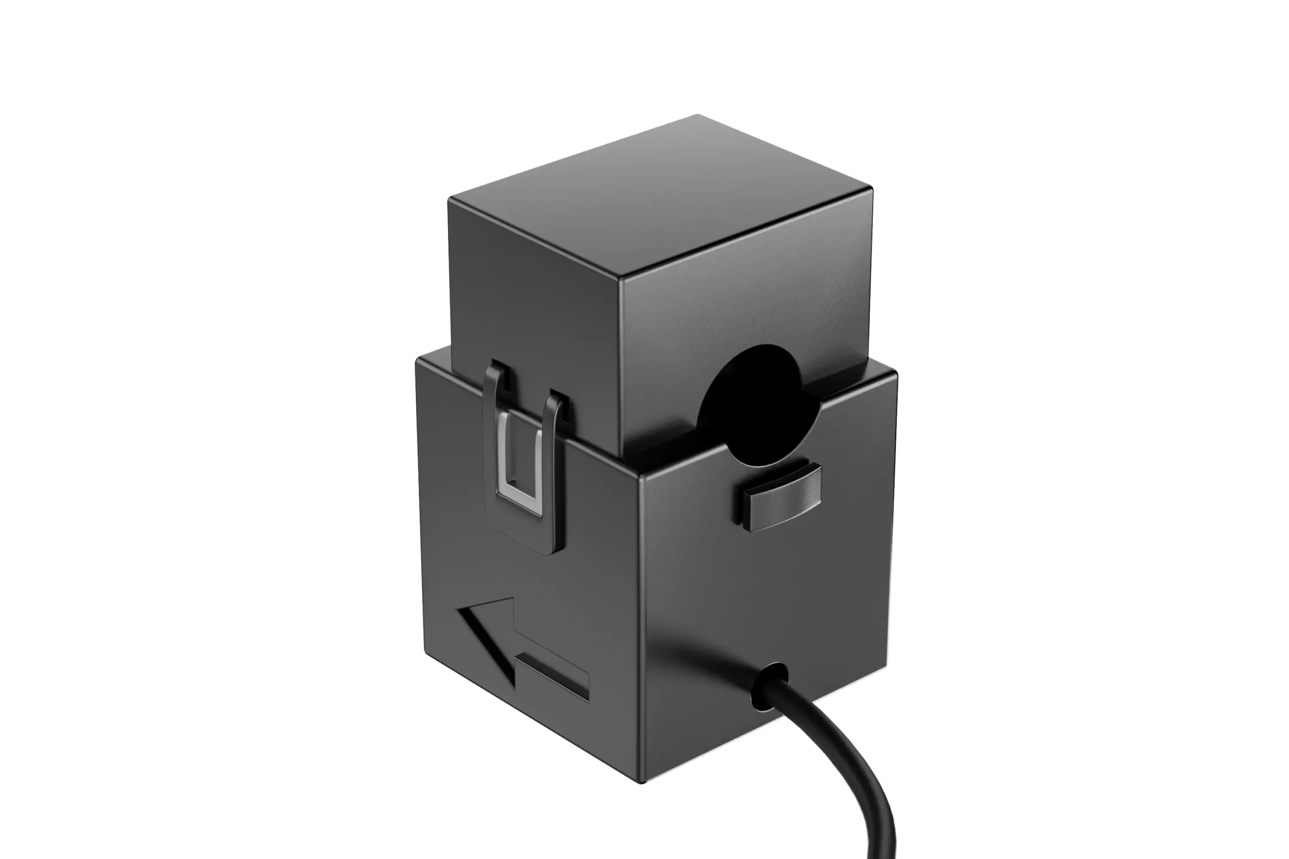
The CT Clamp is a safe and efficient current measurement device, simplifying installation through its non-invasive design. Widely applicable across various current ranges, it provides high-precision real-time monitoring and supports remote surveillance. The CT Clamp serves as a convenient and practical solution in the fields of power system monitoring, industrial automation, and energy management.
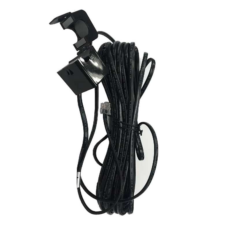
  • High Safety: Non-invasively clamps onto the current conductor
  • Easy Installation: Allows for quick completion of current measurements
  • Real-time Monitoring: Enables swift and accurate capturing of current variations in real-time
  • High Precision: Delivers accurate current measurement results, ensuring data reliability
  • Non-Interference: Non-contact measurement tool that does not affect the circuit, avoiding the introduction of additional resistance or voltage drop

FAQ

The CT (Current Transformer) measures the current flowing between the grid and the site. The inverter uses this information to monitor grid import and export and manage functions such as Zero Export and self-consumption control.

The CT should normally be installed at the grid connection point so that it can measure the total power imported from or exported to the utility grid. The exact installation position should follow the wiring diagram for the specific inverter model.

Yes. CT direction determines how the inverter identifies grid import and export. If the CT is installed in the opposite direction, the grid power direction may be displayed incorrectly. On supported LuxpowerTek systems, this can be corrected using the CT Reverse setting without physically reinstalling the CT.

First confirm that the CT position and wiring are correct. If only the measurement direction is reversed, use the CT Reverse function in the LuxpowerTek monitoring system to correct it. In this case, there is normally no need to physically turn the CT around.

For systems using CT-based export control, yes. The CT measures grid power in real time so the inverter can dynamically adjust its output to minimize unwanted power export to the grid.

This depends on the inverter model and system configuration. Three-phase systems generally require measurement of each phase, while single-phase systems use the applicable single-phase measurement arrangement. Follow the wiring diagram for the specific inverter model.

Check the CT installation position, phase matching, wiring and system configuration. If the import/export direction is simply reversed, use the CT Reverse setting. If the value itself is abnormal, further check the CT connection and phase matching.

The CT should be installed at the required grid measurement point. If the measurement point is far from the inverter, follow LuxpowerTek’s applicable installation requirements for the specific system rather than extending the CT cable without checking the wiring specification.

Both can provide grid power information, but they use different measurement methods. A CT measures current through the conductor, while a smart meter measures electrical parameters and communicates the data to the inverter. The required solution depends on the inverter model and system design.

Check the grid power data on the inverter or LuxCloud while the site is importing or exporting power. The displayed power direction and value should reasonably match the actual operating condition. If not, check the CT position, phase matching and wiring, and use CT Reverse if the direction is reversed.