FAQ
Explore our FAQ for quick answers to your questions. We’re here to assist you every step of the way!
Here are some quick FAQs about our hybrid models. If the answers here don’t solve your query, please feel free to contact us.
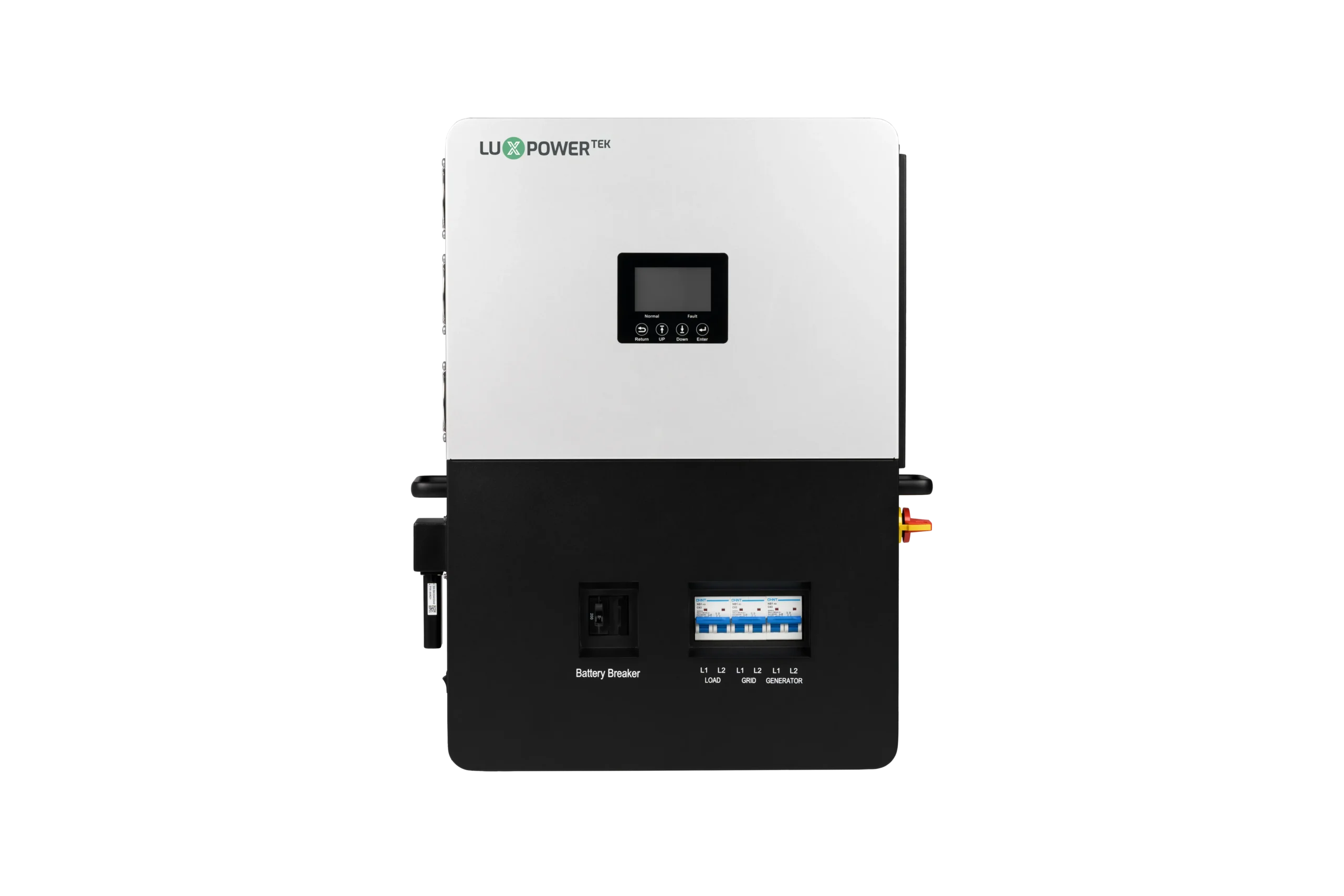
A: Yes, Luxpower 12kW series also facilitates the Generator auto-start function. To enable this feature, ensure your generator supports auto-start functionality. Simply connect a 2-wire cable directly to the dry contact port.
A: This component serves the purpose of preventing dust accumulation and isolating the mainboard. It plays a crucial role in safeguarding the mainboard against the harmful effects of dust, dirt, and other contaminants. Additionally, it provides insulation and shock absorption to ensure optimal functionality and longevity of the mainboard.
A: Before proceeding, please examine the parallel CAN cable and interface board. If necessary, consider replacing the interface board in this unit and conducting a thorough inspection. Should you require additional technical assistance, please don’t hesitate to reach out to our technical support team.
A: Yes, you’ve adjusted the access to Read-Only. However, this setting doesn’t seem to apply when attempting to configure the inverter end using the LCD screen.
A: There’s no safety hazard when you leave home. And you can do the remote monitoring and setting through your app.
Here are some quick FAQs about our off-grid models. If the answers here don’t solve your query, please feel free to contact us.
A: In SNA inverters, the fan operates based on specific power thresholds. When charge or discharge power exceeds 300 watts, the left and middle fans activate. Additionally, the right fan engages when PV power exceeds 300 watts or grid import power exceeds 5000VA.
A: Warning code 00 signifies a “Battery communication fault,” indicating a failure in communication between the battery and the inverter. Additionally, Fault code 00 may suggest a communication issue between control CPUs, prompting a need for a firmware update or system restart. Status code 00 indicates “Standby” mode, indicating the inverter remains in standby due to unmet conditions to switch work modes.
A: If the EPS (power backup) function is activated, the SNA inverter may display a load reading of less than 60 watts even when no load is connected to the EPS output port.
A: The recommended depth of discharge (DOD) depends on system design, including factors like battery capacity and load consumption. For systems with stable grid input aiming for an 80% DOD, adjust “On-grid cutoff SOC or On-grid EOD” to 20%. For systems with unstable or no grid input, set “Off-grid cutoff SOC or discharge cutoff SOC” to 20%, ensuring it’s lower than the “On-grid cutoff SOC” setting.
A: Various conditions such as overload, short circuit, PV overvoltage, overheat, or fan failure can trigger a fault in the inverter, causing it to shut off its output. Any abnormal conditions detected by the DSP will lead to a shutdown.
A: If the battery operates in lithium mode with communication, voltage data originates from the battery’s BMs. However, if voltage readings persist after the battery breaker is turned off, it could indicate the battery was recently active or the inverter operated in charge mode.
A: The displayed current on the monitoring platform reflects data provided by the battery’s BMs. If the BMs accurately report a total current of 200Ah, the monitoring system will display 200Ah. Ensure to consult with the battery supplier for accurate information.
A: Sudden changes in SOC may result from battery SOC calibration issues. Check MaxCellVoltage and MinCellVoltage for imbalanced battery cell voltages.
A: Check the battery status on the home page. If it shows specific codes like 0x10, 0x11, 0x12, 0x13, 0x20, 0x21, 0x22, or 0x23, it indicates the battery has requested forced charging.
A: This could occur due to an instantaneous power outage and recovery. After recovery, manually restart the inverter to clear the fault, or check if the charging power of the inverter exceeds 300W.
A: If the battery operates in lithium mode, voltage data originates from the battery BMS and is unrelated to the inverter. In lead acid mode, SOC reading accuracy may vary, suggesting voltage control as an alternative approach.
Here are some quick FAQs about our AC/DC models. If the answers here don’t solve your query, please feel free to contact us.
A: AC coupling, or AC coupled, primarily refers to a storage system being charged from AC power. Typically used in retrofitting scenarios alongside existing PV systems, AC coupling allows for load compensation and battery charging when grid power is available. During grid outages, the storage system provides a voltage reference for the PV system to continue generating power without grid support.
A: es, both on-grid and off-grid modes are available with a 12kW inverter. The existing PV inverter needs to be connected to the Gen port to enable AC coupling functionality.
A: The ACS3600 cannot achieve true zero export due to certain limitations:
Here are some quick FAQs about our dongle. If the answers here don’t solve your query, please feel free to contact us.
A: Follow these steps to configure the new WiFi password via the app (ensure the new router supports the 2.4GHz frequency band):
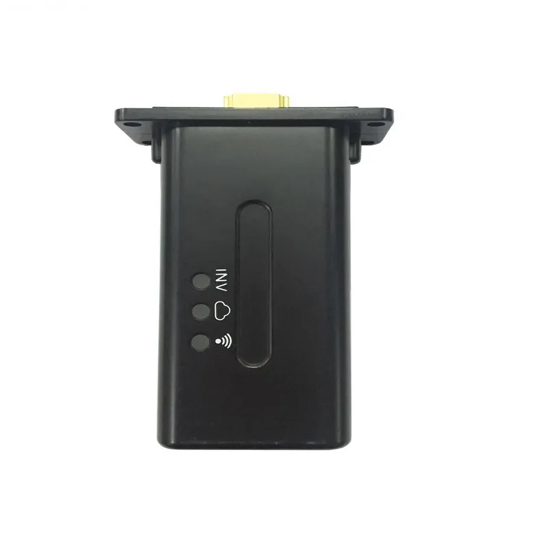
Insert the dongle into the inverter.
Connect your mobile phone or computer to the local hotspot sent by the WiFi dongle when the WiFi LED on the dongle is solid.
Open the Luxpowerview app and navigate to the “WiFi dongle connect” page.
Select your home WiFi network and input the password.
Click “Home WiFi connect” and wait for all three LED indicators to solidify.
A: Ensure that you have inserted the SIM card provided by LUX into the 4G dongle. If issues persist, please provide the 4G dongle serial number, inverter serial number, and SIM card serial number to Luxpower for inquiry regarding the validity period.
A: Troubleshoot by checking the following:
