

What’s Hybrid Solar Solution
Best Smart Energy Storage for Homes & Businesses
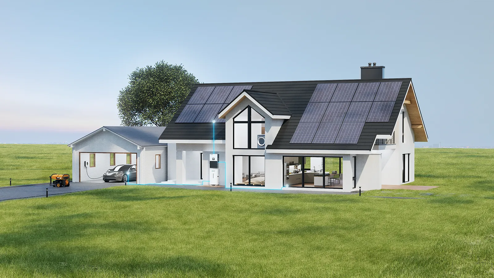
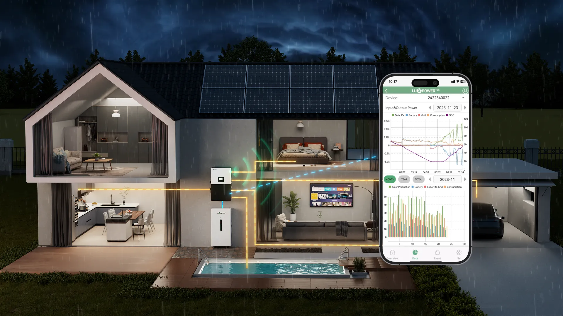
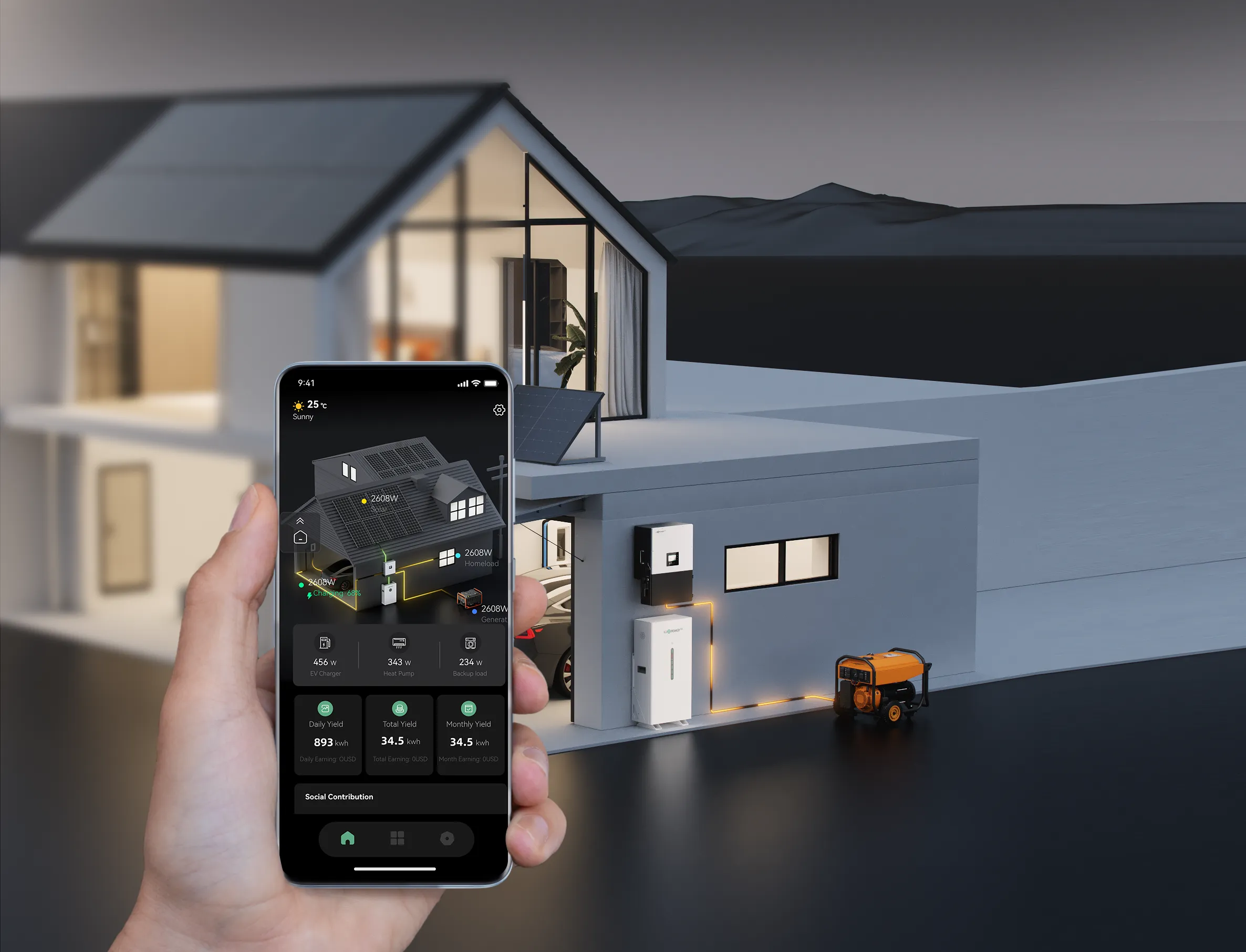
A hybrid solar solution integrates solar panels, battery storage, and grid connectivity, offering a smart, efficient, and reliable energy management system. With the rising demand for energy independence, backup power, and peak shaving, hybrid systems are becoming the best choice for homeowners and businesses looking to optimize their energy use.
🔹 How Does a Hybrid Solar System Work?
✔ Solar Panels generate renewable energy during the day.
✔ Battery Storage saves excess solar power for nighttime or backup use.
✔ Grid Connection ensures power availability when solar or battery reserves are low.
✔ Smart Energy Management allows seamless switching between solar, battery, and grid power.
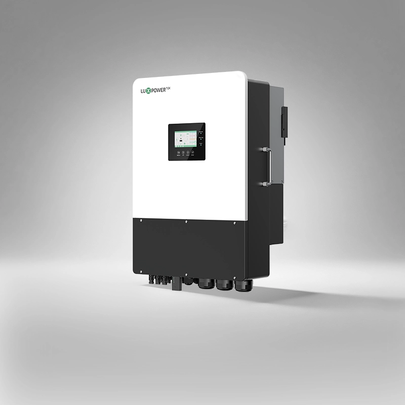
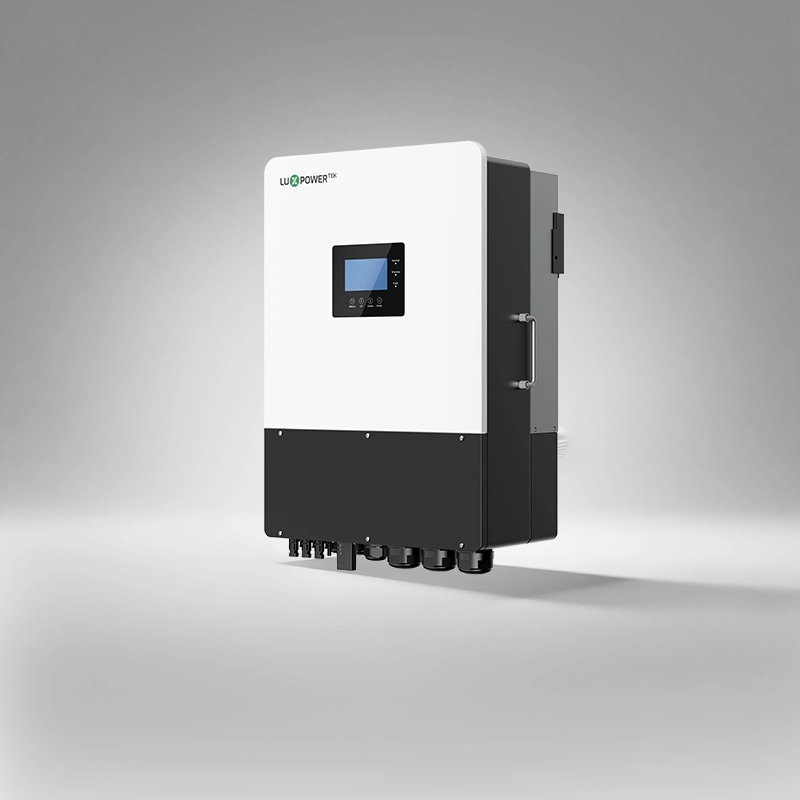
Recommended LuxpowerTek Hybrid Solar Inverters
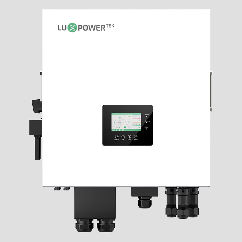
Single-phase Inverter
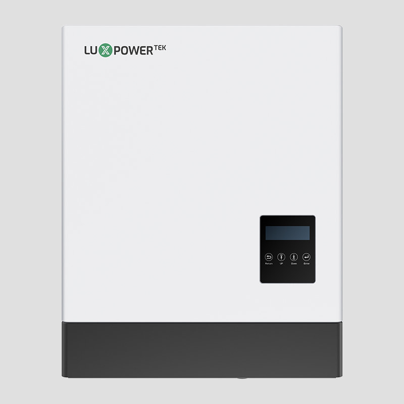
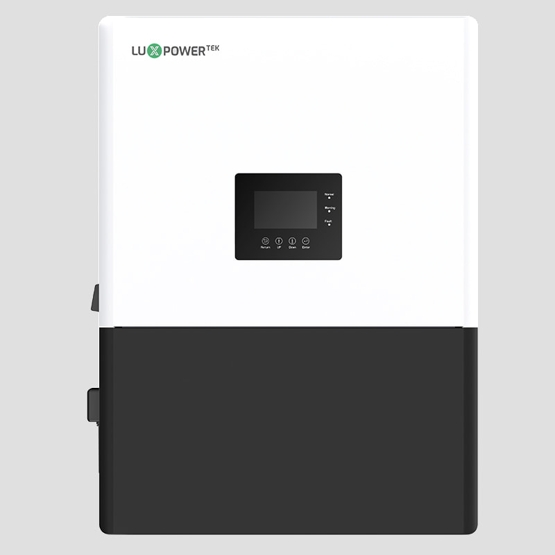
LXP 3-6K
3-6kW Output I Max. 80A charge current
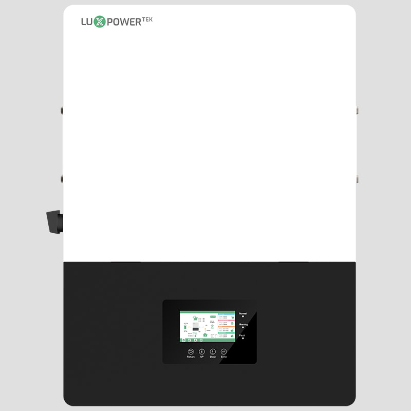
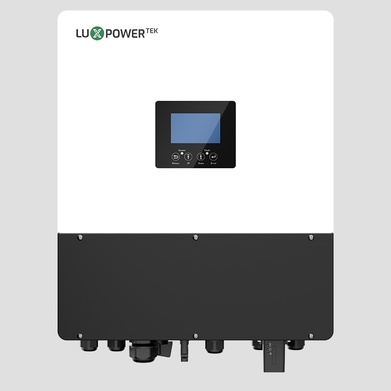
LXP-LB-EU 12K
12kW Output I Max. 18kW of PV input
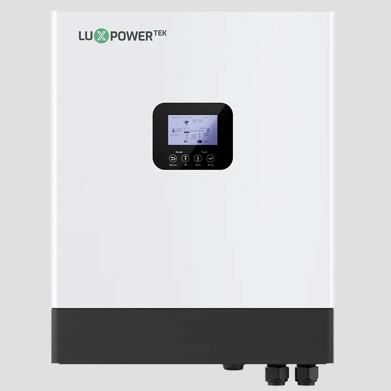
GEN-LB-EU 3-6K
3-6kW Output I Max. 125A charge current
GEN-LB-EU 7-10K
12kW Output I 7-10kW Output I Max. 210A charge current
GEN2-LB-EU 3-6K
3-6kW Output I Max. discharging current 140A
GEN2-LB-EU 7-14K
7-14kW Output I Max. 250A charge current
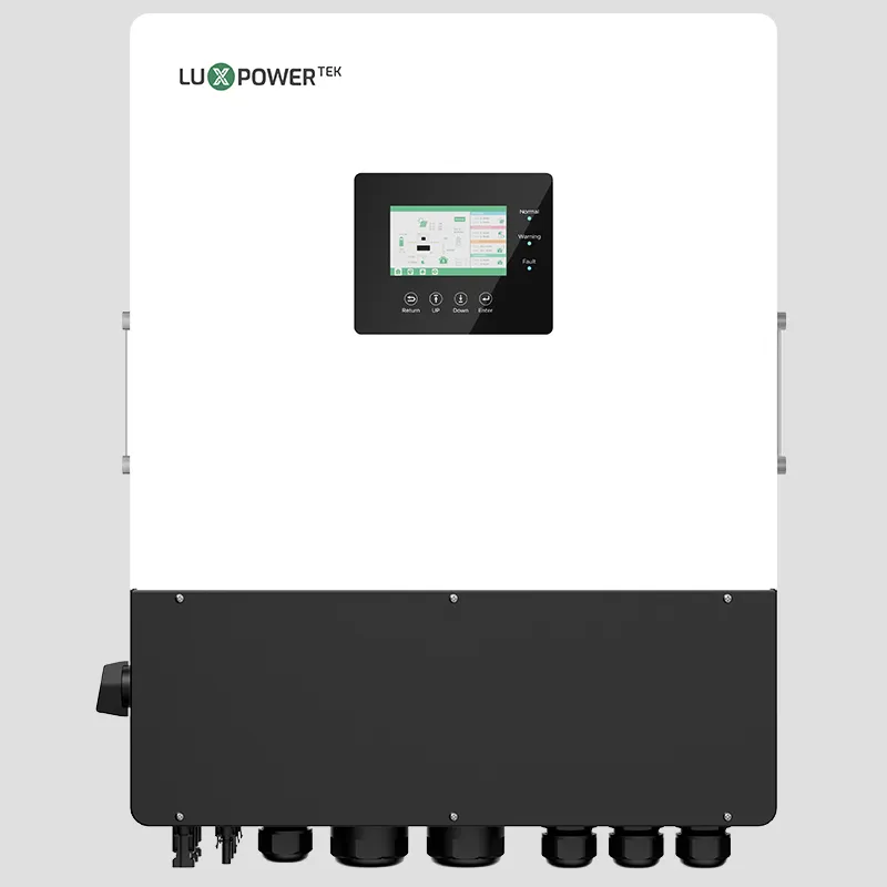
Split-phase Inverter
GEN-HB-US 25K
25kW Output I 120/240V
split-phase output
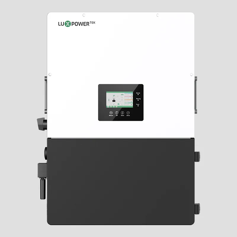
GEN-LB-US 9.6KPRO-16K
12kW Output I Max. discharging current 250A
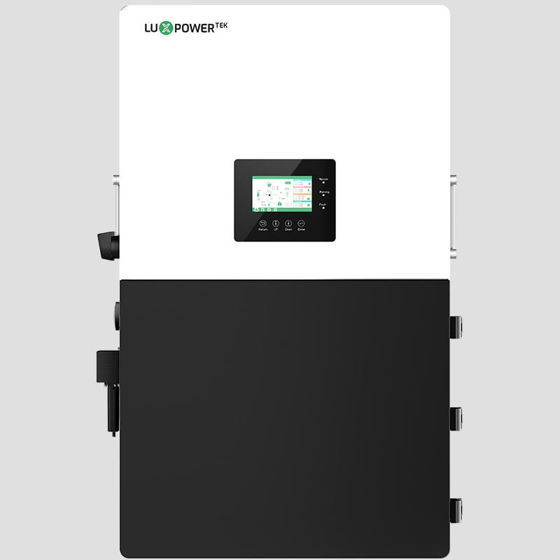
GEN-LB-US 5-13K
5-13kW Output I 120/240V split-phase output
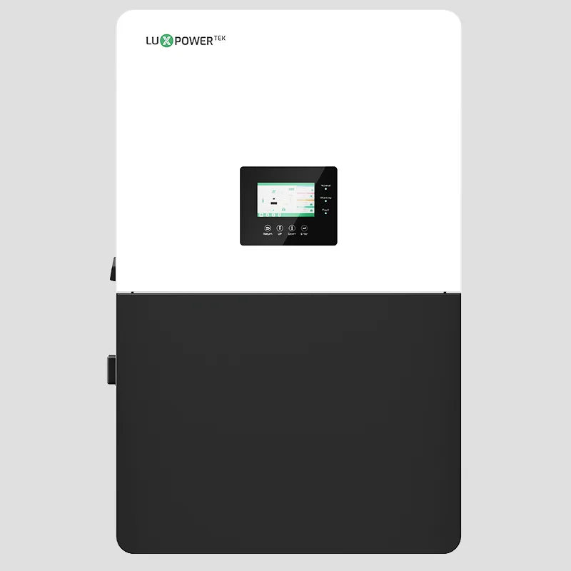
LXP-LB-US 8K/10K
8-10kW Output I Max. PV input 15kW
LXP-LB-US 12K
12kW Output I 200A bypass current
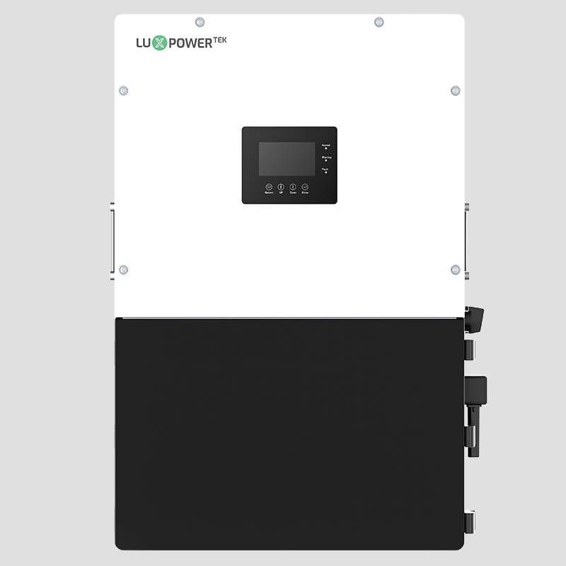
Three-phase Inverter
TRIP2-HB-3P 6-30K
6-30kW Output I up to 45kW PV input
Trip2-LB-3p 5-20K
5-20kW Output I Max. discharging current 250A
TriP 6-30K
6-30kW Output I Max. 30kW UPS output
Why Choose Luxpower Hybrid Solar System?

Seamless Integration
The LuxpowerTek system is compatible with both standby and portable generators, enabling high-power generator support and multiple start options. It can be automatically activated based on a user-defined battery State of Charge (SOC) or manually controlled via the LuxpowerTek App, offering greater flexibility. Additionally, the system periodically runs self-checks on the generator to ensure functionality, providing a reliable and extended backup solution during power outages.Seamless Integration
The LuxpowerTek system is compatible with both standby and portable generators, enabling high-power generator support and multiple start options. It can be automatically activated based on a user-defined battery State of Charge (SOC) or manually controlled via the LuxpowerTek App, offering greater flexibility. Additionally, the system periodically runs self-checks on the generator to ensure functionality, providing a reliable and extended backup solution during power outages.